
Tubing Selection
Proper selection, handling, and installation of tubing, when combined with proper selection of Swagelok® tube fittings, are essential to reliable tubing systems.
The following variables should be considered when ordering tubing for use with Swagelok tube fittings:
- Surface finish
- Material
- Hardness
- Wall thickness

Tubing Surface Finish
Many ASTM specifications cover the above requirements, but they often are not very detailed on surface finish. For example, ASTM A450, a general tubing specification, reads:
- Straightness and Finish
- Finished tubes shall be reasonably straight and have smooth ends free of burrs. They shall have a workmanlike finish. Surface imperfections (Note) may be removed by grinding, provided that a smooth curved surface is maintained, and the wall thickness is not decreased to less than that permitted by this or the product specification. The outside diameter at the point of grinding may be reduced by the amount so removed.
Tubing Material
Our suggested ordering instructions for each type of tubing are shown under the respective tables.
Tubing Outside Diameter Hardness
The key to selecting proper tubing for use with metal Swagelok tube fittings is that the tubing must be softer than the fitting material. Swagelok tube fittings are designed to work properly with the tubing that is suggested in the ordering instructions. Swagelok stainless steel tube fittings have been repeatedly tested successfully with tubing with hardness up to 200 HV and 90 HRB.
Tubing Wall Thickness
The accompanying tables show working pressure ratings of tubing in a wide range of wall thicknesses. Except as noted, allowable pressure ratings are calculated from S values as specified by ASME B31.3, Process Piping. Swagelok tube fittings have been repeatedly tested in both the minimum and maximum wall thicknesses shown. Swagelok tube fittings are not recommended for tube wall thicknesses outside the ranges shown in the accompanying tables for each size.
Tubing Handling
Good handling practices can greatly reduce scratches on tubing and protect the good surface finish that reliable tube manufacturers supply.
- Tubing should never be dragged out of a tubing rack or across a rough surface.
- Tube cutters or hacksaws should be sharp. Do not take deep cuts with each turn of the cutter or stroke of the saw
- Tube ends should be deburred. This helps to ensure that the tubing will go all the way through the ferrules without damaging the ferrule sealing edge.
Tubing Installation

Tubing properly selected and handled, combined with properly installed Swagelok tube fittings, will give you a leaktight system and provide reliable service in a wide variety of applications.
For maximum assurance of reliable performance, use:
-
- properly selected and handled high-quality tubing—such as provided by Swagelok
- Swagelok tube fittings assembled in accordance with catalog instructions
- an appropriate tube support system to limit the movement of tubing and fluid system components.
When installing fittings near tube bends, there must be a sufficient straight length of tubing to allow the tube to be bottomed in the Swagelok fitting
Gas Service
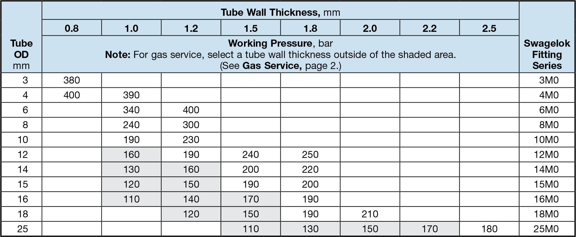
Gases (air, hydrogen, helium, nitrogen, etc.) have very small molecules that can escape through even the most minute leak path. Some surface defects on the tubing can provide such a leak path. As tube outside diameter (OD) increases, so does the likelihood of a scratch or other surface defect interfering with proper sealing. The most successful connection for gas service will occur if all installation instructions are carefully followed and the heavier wall thicknesses of tubing on the accompanying tables are selected.
A heavy-wall tube resists ferrule action more than a thinwall tube, allowing the ferrules to coin out minor surface imperfections. A thin-wall tube offers less resistance to ferrule action during installation, reducing the chance of coining out surface defects, such as scratches. Within the applicable suggested allowable working pressure table, select a tube wall thickness whose working pressure is outside of the shaded areas.
Hydraulic Swaging Unit
A Swagelok multihead hydraulic swaging unit (MHSU) must be used to install 1 1/4, 1 1/2, and 2 in. and 28, 30, 32, 38, and 50 mm Swagelok tube fittings. For more information, see the Gaugeable Tube Fittings and Adapter Fittings catalog (MS-01-140).
Suggested Allowable Working Pressure For Carbon Steel Tubing
Table 1—Fractional Carbon Steel Tubing
Allowable working pressures are calculated from an S value of 15 700 psi (108.2 MPa) for ASTM A179 tubing at –20 to 100°F (–28 to 37°C), as listed in ASME B31.3. For working pressure in accordance with ASME B31.1, multiply by 0.85.

Suggested Ordering Information
High-quality, soft annealed seamless carbon steel hydraulic tubing, ASTM A179 or equivalent. Hardness not to exceed 72 HRB or 130 HV. Tubing to be free of scratches, suitable for bending and flaring.
Suggested Allowable Working Pressure For Carbon Steel Tubing
Table 2—Metric Carbon Steel Tubing
Allowable working pressures are based on equations from ASME B31.3 for DIN 2391 tubing, using a stress value of 113 MPa (16 300 psi) and tensile strength of 340 MPa (49 300 psi).

Suggested Ordering Information
High-quality, soft annealed carbon steel tubing, DIN 2391 or equivalent. Hardness not to exceed 72 HRB or 130 HV. Tubing to be free of scratches, suitable for bending or flaring.
Suggested Allowable Working Pressure For Stainless Steel Tubing
Table 3—Fractional Stainless Steel Seamless Tubing
Allowable working pressures are calculated from an S value of 20 000 psi (137.8 MPa) for ASTM A269 tubing at –20 to 100°F (–28 to 37°C), as listed in ASME B31.3, except as noted.
For Welded Tubing
For welded and drawn tubing, a derating factor must be applied for weld integrity:
- for double-welded tubing, multiply working pressure by 0.85
- for single-welded tubing, multiply working pressure by 0.80.

- For higher pressures, see the Swagelok Medium-Pressure Fittings catalog, MS‑02‑335, or the Swagelok High-Pressure Fittings catalog, MS-01-34.
- Rating based on repeated pressure testing of the Swagelok tube fitting with a 4:1 design factor based upon hydraulic fluid leakage.
Suggested Ordering Information
High-quality, fully annealed (Type 304, 304/304L, 316, 316/316L, 317, 317/317L, 321, 347) (seamless or welded and drawn) stainless steel hydraulic tubing, ASTM A269 and A213, or equivalent. Hardness not to exceed 90 HRB or 200 HV. Tubing to be free of scratches, suitable for bending and flaring. OD tolerances not to exceed ± 0.003 in. for 1/16 in. OD tubing.
Note:
Certain austenitic stainless tubing has an allowable ovality tolerance double the OD tolerance and may not fit into Swagelok precision tube fittings. Dual-certified grades such as 304/304L, 316/316L, and 317/317L meet the minimum chemistry and the mechanical properties of both alloy grades.
Suggested Allowable Working Pressure For Stainless Steel Tubing
Table 4—Metric Stainless Steel Seamless Tubing
Allowable working pressures are calculated from an S value of 137.8 MPa (20 000 psi) for EN ISO 1127 tubing (D4, T4 tolerance for 3 to 12 mm; D4, T3 tolerance 14 to 50 mm), at –28 to 37°C (–20 to 100°F), as listed in ASME B31.3, except as noted.
For Welded Tubing
For welded and drawn tubing, a derating factor must be applied for weld integrity:
- for double-welded tubing, multiply working pressure by 0.85
- for single-welded tubing, multiply working pressure by 0.80.

- Rating based on repeated pressure testing of the Swagelok tube fitting with a 4:1 design factor based upon hydraulic fluid leakage.
Suggested Ordering Information
High-quality, fully annealed (Type 304, 304/304L, 316, 316/316L, 317, 317/317L, 321, 347) stainless steel tubing, EN ISO 1127 or equivalent. Hardness not to exceed 90 HRB or 200 HV. Tubing to be free of scratches, suitable for bending or flaring. OD tolerances not to exceed ± 0.076 mm for 3 mm OD tubing.
Note:
Dual-certified grades such as 304/304L, 316/316L, and 317/317L meet the minimum chemistry and the mechanical properties of both alloy grades.
Suggested Allowable Working Pressure For Copper Tubing
Table 5—Fractional Copper Tubing
Allowable working pressures are calculated from an S value of 6000 psi (41.3 MPa) for ASTM B75 and ASTM B88 tubing at –20 to 100°F (–28 to 37°C), as listed in ASME B31.3 and ASME B31.1.

- Rating based on repeated pressure testing of the Swagelok tube fitting with a 4:1 design factor based upon hydraulic fluid leakage.
Suggested Ordering Information
High-quality, soft annealed seamless copper tubing, ASTM B75 or equivalent. Also soft annealed (Temper O) copper water tube, type K or type L to ASTM B88.
Suggested Allowable Working Pressure For Copper Tubing
Table 6—Metric Copper Tubing
Allowable working pressures are calculated from an S value of 41.3 MPa (6000 psi) for ASTM B75, ASTM B88, and EN 1057 tubing at –28 to 37°C (–20 to 100°F), as listed in ASME B31.3 and ASME B31.1.

- Rating based on repeated pressure testing of the Swagelok tube fitting with a 4:1 design factor based upon hydraulic fluid leakage.
Suggested Ordering Information
High-quality, soft annealed seamless copper tubing, ASTM B75 and EN 1057 or equivalent. Also soft annealed (Temper O) copper water tube, type K or type L to ASTM B88.
Suggested Allowable Working Pressure For Aluminum Tubing
Table 7—Fractional Aluminum Tubing
Allowable working pressures are calculated from an S value of 14 000 psi (96.5 MPa) for ASTM B210, Type 6061-T6 tubing at–20 to 100°F (–28 to 37°C), as listed in ASME B31.3. For working pressure in accordance with ASME B31.1, multiply by 0.85.

- Rating based on repeated pressure testing of the Swagelok tube fitting with a 4:1 design factor based upon hydraulic fluid leakage.
Suggested Ordering Information
High-quality aluminum alloy drawn seamless tubing, ASTM B210 (Type 6061-T6) or equivalent.
Table 8—Metric Aluminum Tubing
Allowable working pressures are calculated from an S value of 96.5 MPa (14 000 psi) for ASTM B210, Type 6061-T6 tubing at–28 to 37°C (–20 to 100°F), as listed in ASME B31.3. For working pressure in accordance with ASME B31.1, multiply by 0.85
Suggested Ordering Information
High-quality aluminum alloy drawn seamless tubing, ASTM B210 (Type 6061-T6) or equivalent.
Suggested Allowable Working Pressure For Additional Alloys
Table 9—Fractional Alloy 400 Tubing
Allowable working pressures are calculated from an S value of 18 700 psi (128.9 MPa) for ASTM B165 tubing at –20 to 100°F (–28 to 37°C), as listed in ASME B31.3 and ASME B31.1.

- Rating based on repeated pressure testing of the Swagelok tube fitting with a 4:1 design factor based upon hydraulic fluid leakage.
Suggested Ordering Information
High-quality, fully annealed seamless alloy 400 hydraulic tubing, ASTM B165 or equivalent. Hardness not to exceed 75 HRB or 137 HV. Tubing to be free of scratches, suitable for bending and flaring. OD tolerances not to exceed ± 0.005 in.
Table 10—Metric Alloy 400 Tubing
Allowable working pressures are calculated from an S value of 128.9 MPa (18 700 psi) for ASTM B165 tubing at –28 to 37°C (–20 to 100°F), as listed in ASME B31.3 and ASME B31.1.

- Rating based on repeated pressure testing of the Swagelok tube fitting with a 4:1 design factor based upon hydraulic fluid leakage.
Suggested Ordering Information
High-quality, fully annealed seamless alloy 400 hydraulic tubing, ASTM B165 or equivalent. Hardness not to exceed 75 HRB or 137 HV. Tubing to be free of scratches, suitable for bending and flaring. OD tolerances not to exceed ± 0.13 mm.
Suggested Allowable Working Pressure For Additional Alloys
Table 11—Fractional Alloy C-276 Tubing
Allowable working pressures are based on equations from ASME B31.3 and ASME B31.1 for a maximum S value of 20 000 psi (137.8 MPa).

- Rating based on repeated pressure testing of the Swagelok tube fitting with a 4:1 design factor based upon hydraulic fluid leakage.
- Assembled with advanced design ferrules.
Suggested Ordering Information
High-quality, fully annealed alloy C-276 tubing, ASTM B622 or equivalent. Hardness not to exceed 100 HRB or 248 HV. Tubing to be free of scratches, suitable for bending and flaring. OD tolerances not to exceed ± 0.005 in.
Table 12—Metric Alloy C-276 Tubing
Allowable working pressures are based on equations from ASME B31.3 and ASME B31.1 for a maximum S value of 137.8 MPa (20 000 psi).

- Rating based on repeated pressure testing of the Swagelok tube fitting with a 4:1 design factor based upon hydraulic fluid leakage.
Suggested Allowable Working Pressure For Additional Alloys
Table 13—Fractional Alloy 20 Tubing
Allowable working pressures are based on equations from ASME B31.3 and ASME B31.1 for a maximum S value of 20 000 psi (137.8 MPa).

- Rating based on repeated pressure testing of the Swagelok tube fitting with a 4:1 design factor based upon hydraulic fluid leakage.
- Assembled with advanced design ferrules.
Suggested Ordering Information
High-quality, fully annealed seamless or welded and drawn alloy 20 tubing, ASTM B729, B468 or equivalent. Hardness not to exceed 95 HRB. Tubing to be free of scratches, suitable for bending and flaring. OD tolerances not to exceed ± 0.005 in.
Table 14—Metric Alloy 20 Tubing
Allowable working pressures are based on equations from ASME B31.3 and ASME B31.1 for a maximum S value of 137.8 MPa (20 000 psi).

Suggested Ordering Information
High-quality, fully annealed seamless or welded and drawn alloy 20 tubing, ASTM B729, B468 or equivalent. Hardness not to exceed 95 HRB. Tubing to be free of scratches, suitable for bending and flaring. OD tolerances not to exceed ± 0.13 mm.
Suggested Allowable Working Pressure For Additional Alloys
Table 15—Fractional Alloy 600 Tubing
Allowable working pressures are based on equations from ASME B31.3 and ASME B31.1 for a maximum S value of 20 000 psi (137.8 MPa).

- Rating based on repeated pressure testing of the Swagelok tube fitting with a 4:1 design factor based upon hydraulic fluid leakage.
Suggested Ordering Information
High-quality, fully annealed, cold drawn #1 temper alloy 600 seamless alloy tubing, ASTM B167 or equivalent. Hardness not to exceed 92 HRB or 198 HV. Tubing to be free of scratches, suitable for bending and flaring. Order to outside diameter and wall thickness only, not to inside diameter, average wall specification. OD tolerances not to exceed ± 0.005 in.
Table 16—Metric Alloy 600 Tubing
Allowable working pressures are based on equations from ASME B31.3 and ASME B31.1 for a maximum S value of 137.8 MPa (20 000 psi).

Suggested Ordering Information
- Rating based on repeated pressure testing of the Swagelok tube fitting with a 4:1 design factor based upon hydraulic fluid leakage.
High-quality, fully annealed, cold drawn #1 temper alloy 600 seamless alloy tubing, ASTM B167 or equivalent. Hardness not to exceed 92 HRB or 198 HV. Tubing to be free of scratches, suitable for bending and flaring. Order to outside diameter and wall thickness only, not to inside diameter, average wall specification. OD tolerances not to exceed ± 0.13 mm.
Suggested Allowable Working Pressure For Additional Alloys
Table 17—Fractional Grade 2 Titanium Tubing
Allowable working pressures are based on equations from ASME B31.3 and a maximum S value of 16 700 psi (115.1 MPa) for ASTM B338 tubing at –20 to 100°F (–28 to 37°C). For working pressure in accordance with ASME B31.1, multiply by 0.85.

- Rating based on repeated pressure testing of the Swagelok tube fitting with a 4:1 design factor based upon hydraulic fluid leakage.
Suggested Ordering Information
High-quality, fully annealed seamless or welded and drawn grade 2 titanium tubing, ASTM B338 or equivalent. Tubing to be free of scratches, suitable for bending. OD tolerances not to exceed ± 0.005 in.
Table 18—Metric Grade 2 Titanium Tubing
Allowable working pressures are based on equations from ASME B31.3 and a maximum S value of 115.1 MPa (16 700 psi) for ASTM B338 tubing at –28 to 37°C (–20 to 100°F). For working pressure in accordance with ASME B31.1, multiply by 0.85.

Suggested Ordering Information
High-quality, fully annealed seamless or welded and drawn grade 2 titanium tubing, ASTM B338 or equivalent. Tubing to be free of scratches, suitable for bending. OD tolerances not to exceed ± 0.13 mm.
Suggested Allowable Working Pressure For Additional Alloys
Table 19—Fractional Alloy 2507 Super Duplex Tubing
Allowable working pressures are calculated from an S value of 38 700 psi (266.8 MPa) for ASTM A789 tubing at –20 to 100°F (–28 to 37°C), as listed in ASME B31.3. For tubing suitable for Alloy 2507 super duplex weld fittings with working pressures calculated based on ASME B31.3 Chapter IX, refer to Alloy 2507 Super Duplex Weld Fittings catalog, MS-01-173. For tubing use at temperatures below –20°F (–28°C), refer to Alloy 2507 Super Duplex Tube Fittings catalog, MS-01-174.

- Pressure ratings based on special wall thickness tolerance for Swagelok Alloy 2507 tubing.
Suggested Ordering Information
High-quality, fully annealed Alloy 2507 super duplex tubing, ASTM A789 or equivalent. Hardness not to exceed 32 HRC. Tubing to be free of scratches, suitable for bending and flaring.
Suggested Allowable Working Pressure For Additional Alloys
Table 20—Fractional Alloy 825 Tubing
Allowable working pressures are calculated from an S value of 23 300 psi (160.6 MPa) for ASTM B163 and ASTM B423 seamless tubing at –20 to 100°F (–28 to 37°C), as listed in ASME BPV 2007 Section II, Part D or ASME B31.3. For ASTM B704, Class 1 or equivalent welded and drawn tubing, multiply working pressure by 0.85.

- Based on repeated pressure testing of the Swagelok tube fitting with 4:1 design factor based upon hydraulic fluid leakage.
Suggested Ordering Information
High-quality, fully annealed seamless alloy 825 tubing, ASTM B163, ASTM B423, or equivalent. Fully annealed welded alloy 825 tubing, ASTM B704, class 1 or equivalent. Hardness not to exceed HR15T90 or 201 HV. Tubing to be free of scratches, suitable for bending and flaring. Wall thickness tolerances not to exceed ± 10 %.
Table 21—Metric Alloy 825 Tubing
Allowable working pressures are calculated from an S value of 160.6 MPa (23 300 psi) for ASTM B163 and ASTM B423 seamless tubing at –28 to 37°C (–20 to 100°F), as listed in ASME BPV 2007 Section II, Part D or ASME B31.3. For ASTM B704, Class 1 or equivalent welded and drawn tubing, multiply working pressure by 0.85.

Suggested Ordering Information
- Based on repeated pressure testing of the Swagelok tube fitting with 4:1 design factor based upon hydraulic fluid leakage.
High-quality, fully annealed seamless alloy 825 tubing, ASTM B163, ASTM B423, or equivalent. Fully annealed welded alloy 825 tubing, ASTM B704, class 1 or equivalent. Hardness not to exceed HR15T90 or 201 HV. Tubing to be free of scratches, suitable for bending and flaring. Wall thickness tolerances not to exceed ± 10 %.
Suggested Allowable Working Pressure For Additional Alloys
Table 22—Fractional Alloy 625 Tubing
Allowable working pressures are calculated from an S value of 26 700 psi (184.1 MPa) for ASTM B444 Grade 2 tubing at –20 to 100°F (–28 to 37°C), as listed in ASME BPV 2007 Section II, Part D, Table 1B; tubing outside diameter and wall thickness tolerances from ASTM B444 for small-diameter tube.

- Based on repeated pressure testing of the Swagelok tube fitting with 4:1 design factor based upon hydraulic fluid leakage.
Suggested Ordering Information
High-quality, fully annealed seamless alloy 625 tubing, ASTM B444, Grade 1 or 2, or equivalent. Hardness not to exceed 25 HRC or 266 HV. Tubing to be free of scratches, suitable for bending and flaring.
Table 23—Metric Alloy 625 Tubing
Allowable working pressures are calculated from an S value of 184.1 MPa (26 700 psi) for ASTM B444 Grade 2 tubing at –28 to 37°C (–20 to 100°F), as listed in ASME BPV 2007 Section II, Part D, Table 1B; tubing outside diameter and wall thickness tolerances from ASTM B444 for small-diameter tube.

Suggested Ordering Information
- Based on repeated pressure testing of the Swagelok tube fitting with 4:1 design factor based upon hydraulic fluid leakage.
High-quality, fully annealed seamless alloy 625 tubing, ASTM B444, Grade 1 or 2, or equivalent. Hardness not to exceed 25 HRC or 266 HV. Tubing to be free of scratches, suitable for bending and flaring.
Suggested Allowable Working Pressure For Additional Alloys
Table 24—Fractional Alloy 6Mo Tubing
Allowable working pressures are calculated from an S value of 27 100 psig (186.8 MPa) for ASTM A213 tubing at –20 to 100°F (–28 to 37°C), as listed in ASME B31.3 and ASME B31.1, except as noted.
For Welded Tubing
For welded and drawn tubing, a derating factor must be applied for weld integrity:
- for double-welded tubing, multiply working pressure by 0.85
- for single-welded tubing, multiply working pressure by 0.80.

- Based on repeated pressure testing of the Swagelok tube fitting with 4:1 design factor based upon hydraulic fluid leakage.
Suggested Ordering Information
High-quality, fully annealed seamless or welded and drawn alloy (254, AL6XN, 925, 926) hydraulic tubing, ASTM A269 or ASTM A213, or equivalent. Hardness not to exceed 96 HRB. Tubing to be free of scratches, suitable for bending and flaring.
Suggested Allowable Working Pressure For Additional Alloys
Table 25—Metric Alloy 6Mo Tubing
Allowable working pressures are calculated from an S value of 186.8 MPa (27 100 psig) for ASTM A213 tubing at –20 to 100°F (–28 to 37°C), as listed in ASME B31.3 and ASME B31.1, except as noted.
For Welded Tubing
For welded and drawn tubing, a derating factor must be applied for weld integrity:
- for double-welded tubing, multiply working pressure by 0.85
- for single-welded tubing, multiply working pressure by 0.80.
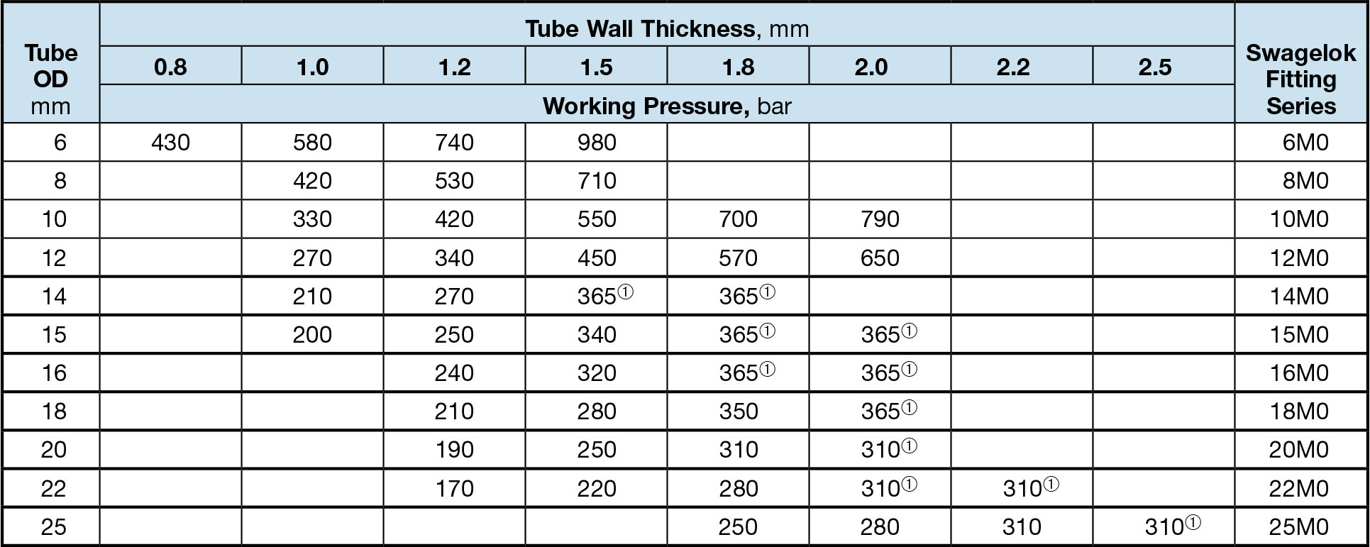
- Based on repeated pressure testing of the Swagelok tube fitting with 4:1 design factor based upon hydraulic fluid leakage.
Suggested Ordering Information
High-quality, fully annealed seamless or welded and drawn alloy (254, AL6XN, 925, 926) hydraulic tubing, ASTM A269 or ASTM A213, or equivalent. Hardness not to exceed 96 HRB. Tubing to be free of scratches, suitable for bending and flaring.
Pressure Ratings At Elevated Temperatures
Table 26—Elevated Temperature Factors

- Based on 375°F (190°C) max.
- Dual-certified grades such as 304/304L, 316/316L, and 317/317L meet the requirements for the lower maximum carbon content of the L grades and the higher minimum yield and tensile strength of the non-L grades.
- Based on the lower derating factor for stainless steel, in accordance with ASME B31.3.
- Use of 2507 super duplex stainless steel at temperatures above 482°F (250°C) causes microstructural changes that lead to embrittlement and loss of corrosion resistance. Derating factor at 482°F (250°C) is 0.81.